VR2-0508-LHT
1.1
400/3/50
4.7
VR2-0509-LHM
1.5
230/1/50
18.4
VR2-0509-LHT
1.5
400/3/50
6
VR2-0511-LHM
1.5
230/1/50
18.4
VR2-0511-LHT
1.5
400/3/50
6
VR2-0512-LHM
2.2
230/1/50
25
VR2-0512-LHT
2.2
400/3/50
9.3
VR2-0514-LHM
2.2
230/1/50
25
VR2-0514-LHT
2.2
400/3/50
9.3
VR2-0516-LHM
2.2
230/1/50
25
VR2-0516-LHT
2.2
400/3/50
9.3
VR2-0518-LHM
3
230/1/50
12.4
VR2-0521-LHT
3
400/3/50
12.4
VR2-1003-LHM
1.1
230/1/50
8.2
VR2-1003-LHT
1.1
400/3/50
4.7
VR2-1004-LHM
1.5
230/1/50
18.4
VR2-1004-LHT
1.5
400/3/50
6
VR2-1005-LHM
2.2
230/1/50
25
VR2-1005-LHT
2.2
400/3/50
9.3
VR2-1006-LHM
2.2
230/1/50
25
VR2-1006-LHT
2.2
400/3/50
9.3
VR2-1007-LHT
3
400/3/50
12.4
VR2-1008-LHT
3
400/3/50
12.4
VR2-1009-LHT
4
400/3/50
15.3
VR2-1011-LHT
4
400/3/50
15.3
VR2-1502-LHM
2.2
230/1/50
25
VR2-1502-LHT
2.2
400/3/50
9.3
VR2-1503-LHT
3
400/3/50
12.4
VR2-1504-LHT
4
400/3/50
15.3
VR2-1505-LHT
4
400/3/50
15.3
VR2-1506-LHT
5.5
400/3/50
20.8
VR2-1507-LHT
5.5
400/3/50
20.8
VR2-1509-LHT
7.5
400/3/50
28
VR2-2202-LHM
2.2
230/1/50
25
VR2-2202-LHT
2.2
400/3/50
9.3
VR2-2203-LHT
3
400/3/50
12.4
VR2-2204-LHT
4
400/3/50
15.3
VR2-2205-LHT
5.5
400/3/50
20.8
VR2-2207-LHT
7.5
400/3/50
28
VR3-0508-LHM
1.1
230/1/50
12.3
VR3-0508-LHT
1.1
400/3/50
7.1
VR3-0509-LHM
1.5
230/1/50
27.6
VR3-0509-LHT
1.5
400/3/50
9.1
VR3-0511-LHM
1.5
230/1/50
27.6
VR3-0511-LHT
1.5
400/3/50
9.1
VR3-0512-LHM
2.2
230/1/50
37.5
VR3-0512-LHT
2.2
400/3/50
13.9
VR3-0514-LHM
2.2
230/1/50
37.5
VR3-0514-LHT
2.2
400/3/50
13.9
VR3-0516-LHM
2.2
230/1/50
37.5
VR3-0516-LHT
2.2
400/3/50
13.9
VR3-0518-LHT
3
400/3/50
18.6
VR3-0521-LHT
3
400/3/50
18.6
VR3-1003-LHM
1.1
230/1/50
12.3
VR3-1003-LHT
1.1
400/3/50
7.1
VR3-1004-LHM
1.5
230/1/50
27.6
VR3-1004-LHT
1.5
400/3/50
9.1
VR3-1005-LHM
2.2
230/1/50
37.5
VR3-1005-LHT
2.2
400/3/50
13.9
VR3-1006-LHM
2.2
230/1/50
37.5
VR3-1006-LHT
2.2
400/3/50
13.9
VR3-1007-LHT
3
400/3/50
18.6
VR3-1008-LHT
3
400/3/50
18.6
VR3-1009-LHT
4
400/3/50
22.9
VR3-1011-LHT
4
400/3/50
22.9
VR3-1502-LHM
2.2
230/1/50
37.5
VR3-1502-LHT
2.2
400/3/50
13.9
VR3-1503-LHT
3
400/3/50
18.9
VR3-1504-LHT
4
400/3/50
22.9
VR3-1505-LHT
4
400/3/50
22.9
VR3-1506-LHT
5.5
400/3/50
31.2
VR3-1507-LHT
5.5
400/3/50
31.2
VR3-1509-LHT
7.5
400/3/50
42
VR3-2202-LHM
2.2
230/1/50
37.5
VR3-2202-LHT
2.2
400/3/50
13.9
VR3-2203-LHT
3
400/3/50
18.6
VR3-2204-LHT
4
400/3/50
22.9
VR3-2205-LHT
5.5
400/3/50
31.2
VR3-2207-LHT
7.5
400/3/50
42
Brochure
|
A technical overview of the Dutypoint VR. |
|
Case studies
|
DUTYPOINT WINS IN GRANDSTAND FINISH |
|
Consultant Specification Templates
|
Consultant Specification Template for VR booster sets.
|
|
Certificates
|
VR Booster - WRAS Approval Certification. |
|
|
VR Booster - Kiwa Regulation 4 (KUKreg4) Certification. |
|
Manuals
|
Operation and maintenance manual for the VR booster sets equipped with a Hydrovar inverter. |
|
|
Operation & Maintenance Manual for VR booster sets equipped with Vasco inverters - models containing -LVT or -LVM. |
|
|
Operation and maintenance manual for VR cold water booster set fitted with new Lowara Hydrovar HVL intelligent controller. |
|
Control Panel Diagrams
|
Control Panel Wiring Diagram for Twin Pump, Single Phase (240v) Booster Sets. |
|
|
Control Panel Wiring Diagram for Twin Pump, Three Phase (400v) Booster Sets. |
|
|
Control Panel Wiring Diagram for Triple Pump, Single Phase (240v) Booster Sets. |
|
|
Control Panel Wiring Diagram for Triple Pump, Three Phase (400v) Booster Sets. |
|
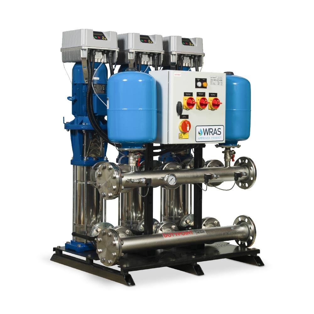
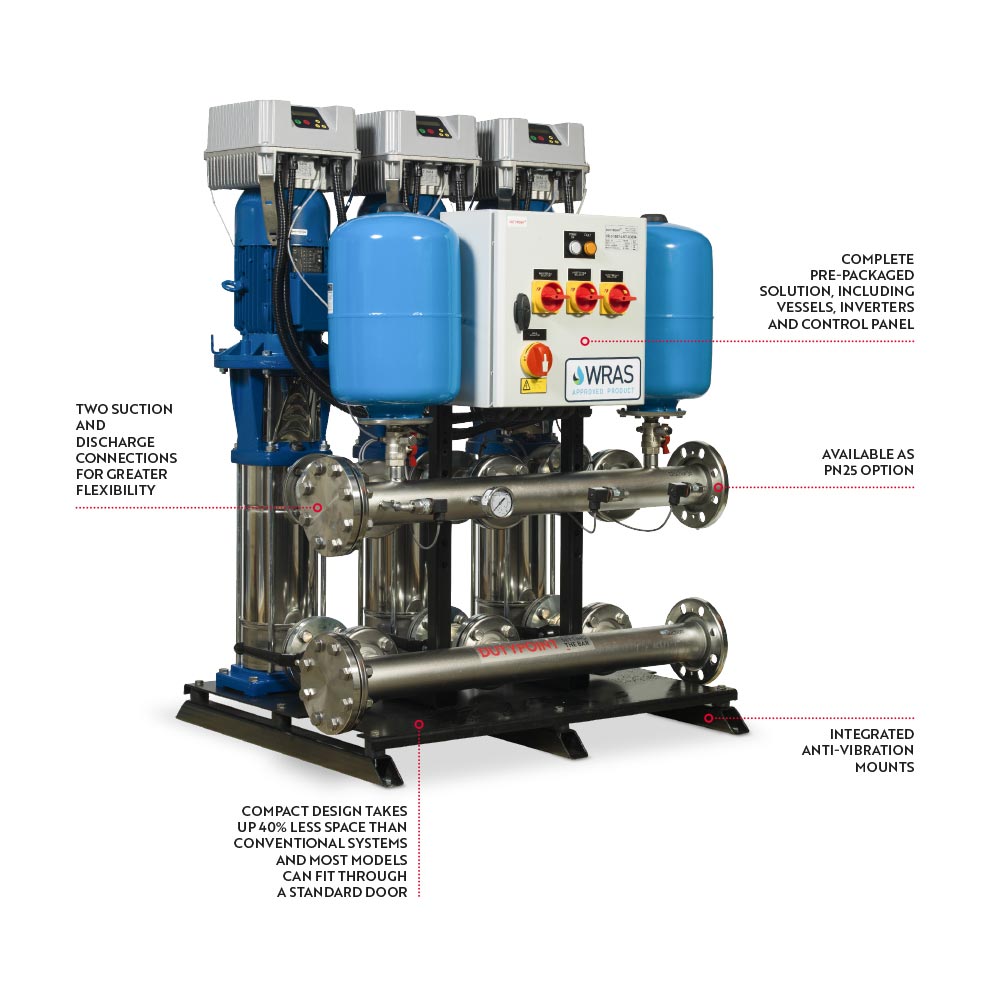
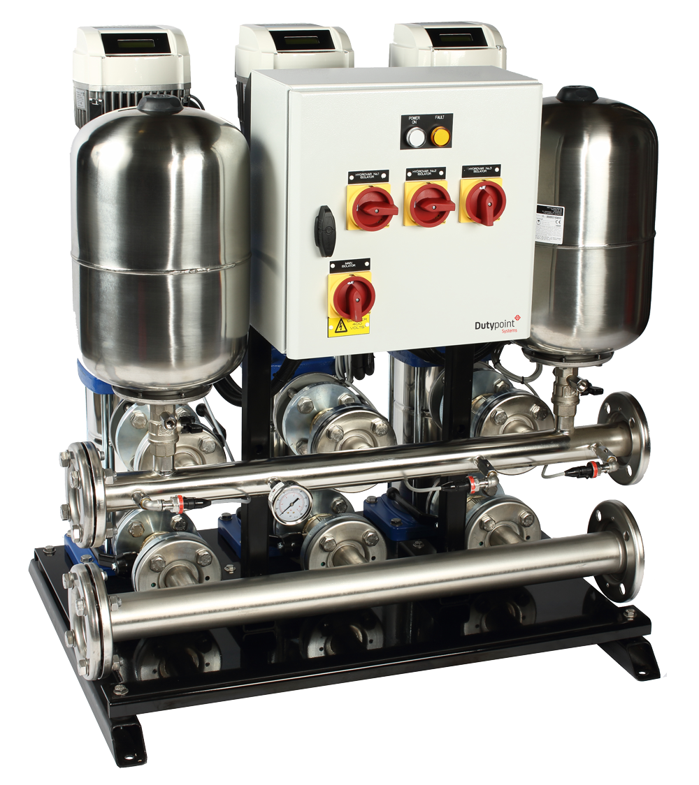
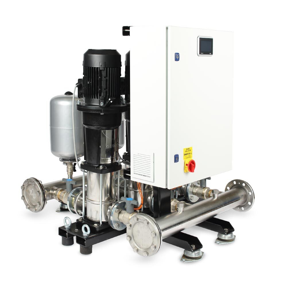
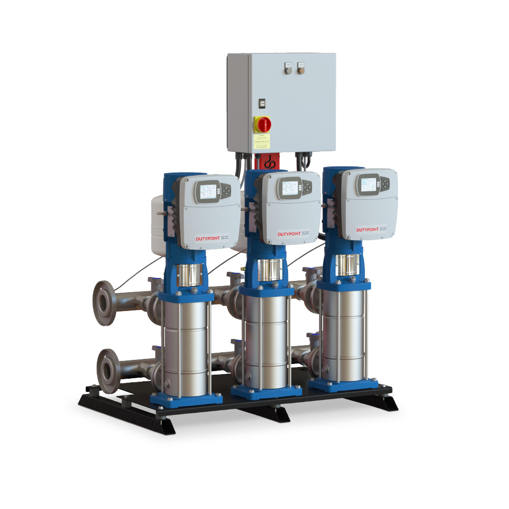
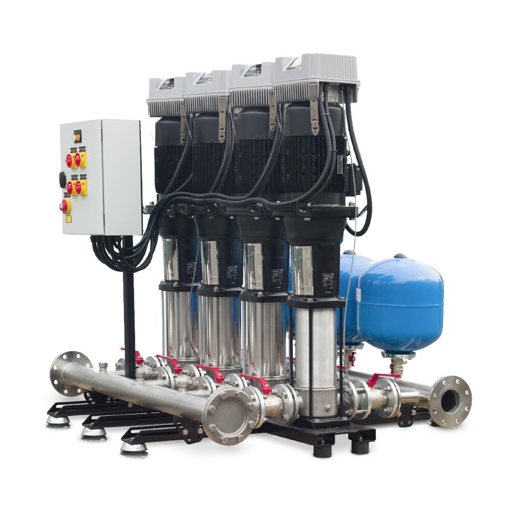
Product overview
– Multistage vertical pumps
– Low-water cut-out contacts in panel
– Anti-vibration mounts reduce system noise
– Pressure set point adjustment
– Hours run recorders
– Local electrical isolation and MCB protection
– IP55-rated control panel allows for simple and safe maintenance
– Cyclic duty changeover ensures even wear across pumps
– Common fault volt-free contact for connection to building management systems
– RS485 connections for connection to Modbus
Pressure range
2 – 16 bar
Max system pressure
16 bar
Controller type
Motor-mounted inverter
Max system temperature
40°C
Noise data
Motor at 2900 rpm < 70LpA (dB +/-2)*
*More specific details available on request.
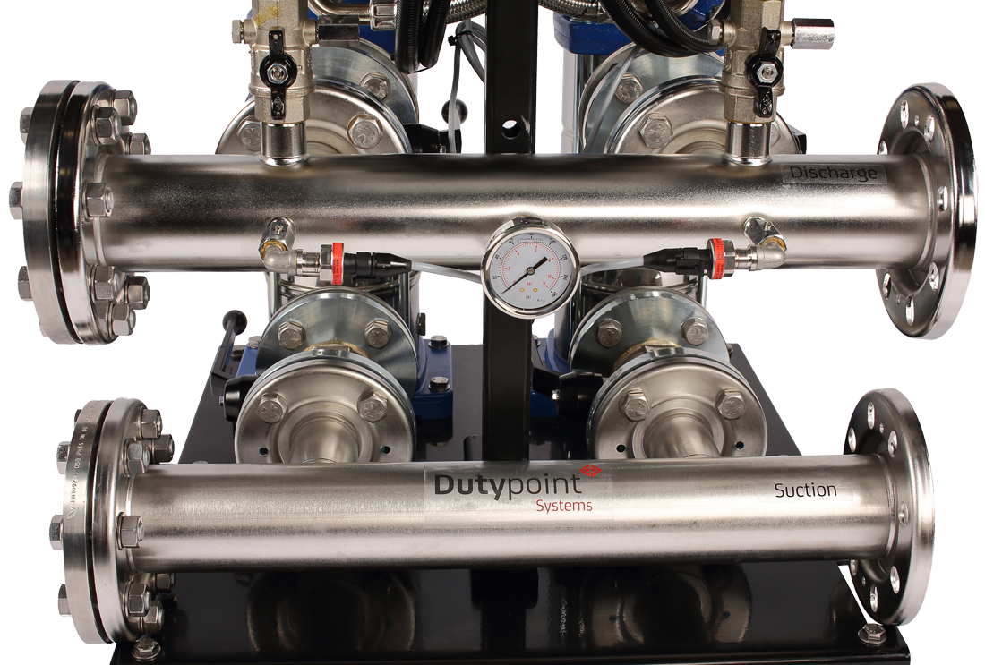
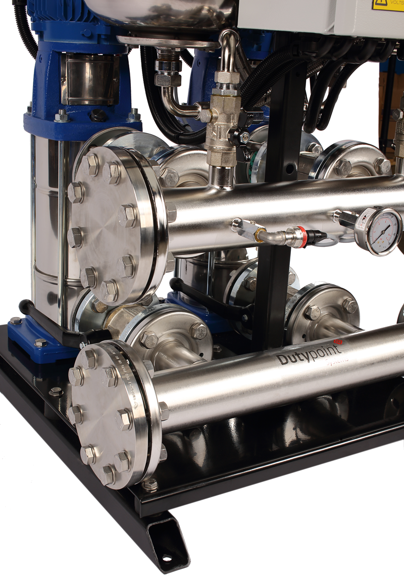
Manifolds
AISI 304 stainless steel
Isolation valves
Nickel-plated brass
Non-return valves
AISI 304 stainless steel
Pressure transducers
AISI 304 stainless steel
Pump casing
AISI 304 stainless steel
Pump impellers
AISI 316L stainless steel
Mechanical seals
Silicon carbide, graphite, EPDM
Pressure vessels
Mild steel, WRAS approved
Base plate
Powder-coated mild steel


